


Library of standard and complex parts
- Search filter
- Fasteners
- Standard profiles
- Machine accessorie
- Pipeline fittings
- Reamers
- Circuit elements symbols
- Technical sketches
- Electric motors
- Gear boxes
Mechanica is nanoCAD’s 2D drafting and 3D mechanical design module. It is based on an advanced parametric engine, and works with a large library of standard parts. It enables users to carry out fast development of high-quality mechanical engineering drawings and project documentation.
Download nownanoCAD platform provides you with a full set of basic and advanced design tools for creating and editing 2D/3D objects. It offers multiple drawing and editing methods for most geometric elements. nanoCAD platform is the base on which you build a more powerful CAD system to your specifications.
Mechanica extends the nanoCAD platform with an array of mechanical drawing and engineering calculation utilities coupled with a vast library of standard and user-defined parts. The synergy speeds up the parametric drafting process.
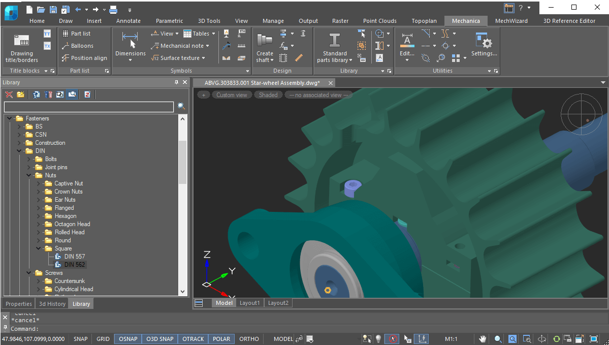
Mechanica’s parts database contains a vast collection of parametric and object-dependent elements, including three-dimensional ones. When you change the parameters of a part, all associated parts in the drawing also change automatically, according to their database values. This powerful tool generates design variations, which improve the design quality.
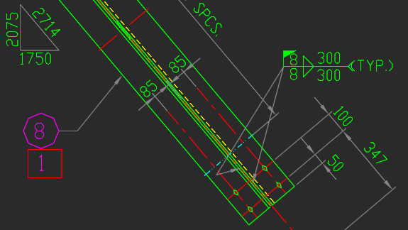
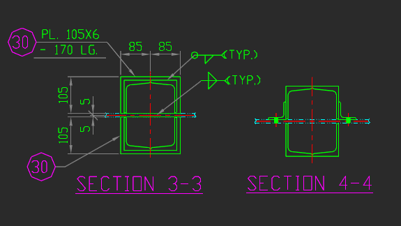
With Mechanica, you quickly make drawings based on international standards using these tools:
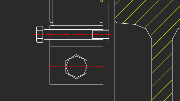
Mechanica offers flexibility in handling bolt and rivet functions:
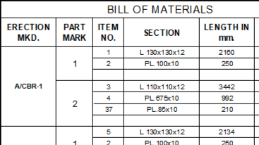
Mechanica’s BOM tools create bills of material of parts linked to drawings. BOM tables can contain the following items:
Mechanica supports dimension styles, which are named collection of dimension settings that control the appearance of dimensions, such as the arrowhead, the text placement, and display of tolerances. It includes styles preset for a number of local and international standards.
Mechanica generates detail views as objects that are updated by the MCREGEN command when the source model changes. When at least part of a scaled object falls into the view frame, then its scale is applied to the entire detail view.
Mechanica’s powerful engineering calculators handle gear strengths, complex cross-sections of geometric properties with arbitrary axes, fasteners, bearing life at given load conditions, and more. Results of calculations are generated automatically as reports that show all formulas and ISO references used for the calculations.
nanoCAD can be used on its own as a cost-effective DWG-editor, or customized with essential modules: Construction, Mechanica, Raster, Topoplan and 3D Solid Modeling.

Lot B6-X3. My Dinh 1 Urban Area
Cau Dien, Nam Tu Liem, Hanoi.

097 196 0055
Mon-Fri 8am-5pmGet Subscribed!


